

Optical Ground Wire (OPGW) cables are revolutionizing power grid communication by combining lightning protection with high-speed fiber optics. However, improper installation can lead to costly failures, downtime, and safety risks. Whether upgrading a national grid or deploying renewable energy networks, here are the 5 critical factors utility engineers and project managers must prioritize for a successful OPGW installation.
1. Structural Compatibility with Existing Power Lines
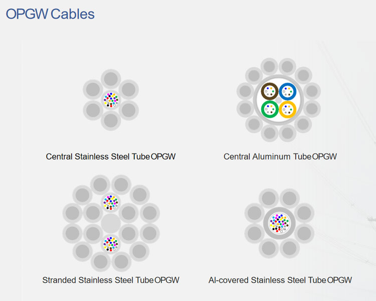
OPGW cables replace traditional ground wires on transmission towers, but their weight and diameter must align with tower design:
Tension Limits: Exceeding tower load capacity risks structural damage. Calculate sag-tension values using software like PLS-CADD.
Diameter Matching: Ensure OPGW’s outer diameter matches existing ground wires (typically 10–20 mm) to avoid tower arm reconfiguration.
Case Study: A Canadian utility avoided $1.2M in retrofitting costs by selecting OPGW with a 14.6mm diameter, matching legacy infrastructure.
Keyword Tip: Use terms like “OPGW structural compatibility” or “transmission tower load capacity.”
2. Environmental Resilience
OPGW cables face extreme weather, from ice storms to desert heat. Prioritize:
Corrosion Resistance: Aluminum-clad steel (ACS) or stainless steel layers prevent rust in coastal or high-humidity regions.
Temperature Range: Choose cables rated for -40°C to +80°C to avoid performance degradation.
Ice/Wind Load: Select OPGW meeting IEEE 1138 standards for 1-inch radial ice and 120 mph winds.
Example: After a 2023 Icelandic storm, OPGW with 150 mph wind resistance maintained 99.9% uptime, while traditional cables failed.
3. Fiber Capacity and Future-Proofing
OPGW’s fiber count determines communication bandwidth. Plan for long-term needs:
Current Requirements: 24–48 fibers suffice for basic grid monitoring.
Future Expansion: Opt for 144+ fibers to support 5G backhaul, smart meters, or leased telecom networks.
Fiber Type: Single-mode fibers (SMF) are standard, but consider bend-insensitive fibers for mountainous terrains.
Pro Tip: Keywords like “high-capacity OPGW” or “future-proof power line fiber” align with SEO goals.
4. Installation Methodology and Safety
Improper installation causes 60% of OPGW failures. Follow best practices:
Stringing Equipment: Use tensioners and dynamometers to maintain ≤20% of rated tensile strength during installation.
Jointing Techniques: Fusion splicing ensures ≤0.05 dB loss per splice; avoid mechanical splices in high-vibration areas.
Safety Protocols: OSHA-compliant training for crews handling live lines or working at heights.
Data Point: Proper tensioning reduced cable replacements by 45% in a 2024 Australian grid project.
5. Compliance with International Standards
Adherence to regulations ensures reliability and avoids penalties:
IEC 60794: Defines mechanical/optical performance for OPGW.
IEEE 1138: Covers electrical and environmental testing.
Local Grid Codes: E.g., FERC standards in the U.S. or CENELEC in Europe.
Checklist:
☑️ Third-party certification reports (e.g., ISO9001, UL, CE).
☑️ Lightning current withstand (typically 100–200 kA).
☑️ Documented attenuation values (≤0.22 dB/km at 1550 nm).
FAQs: Addressing Common OPGW Installation Queries
Q: Can OPGW be installed on live power lines?
A: Yes—but only with specialized hot-line installation tools and trained crews.
Q: How long does OPGW installation take?
A: 1–3 weeks per 100 miles, depending on terrain and crew expertise.
Q: What’s the maximum span length for OPGW?
A: Typically 300–500 meters, but engineered solutions can extend to 800 meters.
Conclusion: Precision Planning Pays Off
OPGW installation is a high-stakes process where cutting corners risks grid reliability and ROI. By prioritizing structural compatibility, environmental resilience, fiber scalability, safety protocols, and regulatory compliance, utilities can ensure decades of seamless operation. Partner with vendors offering end-to-end support—from design to post-installation audits—to maximize success.