
All-Dielectric Self-Supporting (ADSS) cable is a critical component in modern fiber optic networks, particularly for aerial installations along power transmission lines. Unlike traditional optical cables, ADSS cables are entirely non-metallic, combining dielectric strength with self-supporting capabilities. Designing and producing ADSS cables requires balancing mechanical robustness, environmental resilience, and optical performance. This article outlines the key steps and considerations for creating high-quality ADSS cables tailored to specific applications.
1. Understanding ADSS Cable Requirements
ADSS cables must withstand harsh environmental conditions while maintaining signal integrity. Key design parameters include:
- Mechanical Load: Wind, ice, and gravitational forces.
- Span Length: Distance between supporting structures (e.g., utility poles).
- Electrical Environment: Proximity to high-voltage power lines (anti-corona and arc resistance).
- Optical Performance: Attenuation, bend radius, and bandwidth.
2. Core Design Considerations
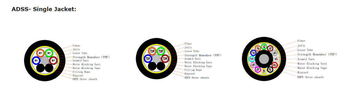
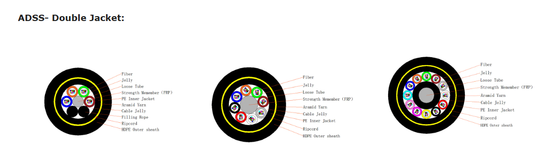
A. Material Selection
Central Strength Member: Aramid yarn (e.g., Kevlar) or fiberglass-reinforced plastic (FRP) provides tensile strength.
Buffer Tubes: PBT (polybutylene terephthalate) tubes house optical fibers, offering flexibility and protection.
Outer Sheath: Dual-layer HDPE (high-density polyethylene) with UV stabilizers for weather resistance.
B. Mechanical Strength Calculations
Use formulas like Catenary Equation to determine sag and tension under maximum load:

Where:
T = Horizontal tension
w = Weight per unit length
S = Span length
d = Sag
C. Electrical Performance
Anti-Corona Design: Ensure sufficient distance between the cable surface and power lines to prevent partial discharges.
Grounding: Incorporate dielectric armor rods to mitigate electric field effects.
D. Optical Fiber Arrangement
Loose Tube vs. Central Core: Loose tube designs (with gel filling) protect fibers from moisture and micro bends.
Fiber Count: Typically ranges from 12 to 144 fibers, depending on application.
3. Production Process
Step 1: Fiber Preparation
- Strip and clean optical fibers.
- Arrange fibers into buffer tubes with water-blocking gel.
Step 2: Strength Member Integration
- Wrap aramid yarn or FRP rods around the central buffer tube.
- Apply tension to ensure uniform distribution.
Step 3: Sheath Extrusion
- Inner Sheath: Extrude black HDPE for UV protection.
- Outer Sheath: Add colored stripes for identification and a smooth surface to reduce ice/wind adhesion.
Step 4: Cabling and Stranding
- Helically stranded layers improve flexibility and tensile strength.
- Include ripcords for easy field installation.
Step 5: Quality Testing
- Mechanical Tests: Tensile strength, crush resistance, and cyclic flexing.
- Environmental Tests: Temperature cycling (-40°C to +70°C), UV exposure, and salt spray.
- Optical Tests: Attenuation (OTDR), chromatic dispersion, and polarization mode dispersion (PMD).
4. Standards and Certifications
- ADSS cables must comply with:
- IEC 60794-1-2: Generic specifications for optical cables.
- IEEE 1138: Standards for ADSS cables on power utility lines.
- GR-20-CORE: Reliability requirements for fiber optic cables.
5. Application-Specific Customization
- High Wind/Ice Zones: Increase aramid yarn density and use thicker HDPE sheaths.
- Fire-Prone Areas: Add flame-retardant (LSZH) materials.
- Long Spans: Optimize catenary calculations and use high-modulus FRP rods.
6. Installation Best Practices
Sag Tension Control: Use dynamometers to avoid over-tensioning.
Vibration Dampers: Install spiral vibration dampers in high-wind areas.
Clearance from Power Lines: Maintain a minimum distance (e.g., 1 meter per 10 kV).
7. Common Pitfalls to Avoid
1. Underestimating Ice Load: Leads to cable rupture in cold climates.
2. Poor Sheath Adhesion: Causes sheath slippage under thermal expansion.
3. Ignoring DC Voltage Stress: Accelerates aging near high-voltage lines.
8. Case Study: ADSS in Mountainous Terrain
A telecom operator in the Swiss Alps deployed ADSS cables with:
- Enhanced Ice Resistance: 5 mm thick HDPE sheath.
- High Tensile FRP: 30% stronger than standard aramid.
- Vibration Dampers: Every 15 meters to counter wind-induced oscillations.
- Result: Zero failures after 5 years, despite -30°C winters and 150 km/h winds.
9. Future Trends
1. Smart ADSS Cables: Integrated strain/temperature sensors for real-time monitoring.
2. Eco-Friendly Materials: Recyclable HDPE and bio-based gels.
3. Higher Fiber Counts: Up to 288 fibers for 5G backhaul densification.
Conclusion
Designing and producing the right ADSS cable demands a multidisciplinary approach—combining material science, mechanical engineering, and optical physics. By rigorously adhering to standards, customizing for environmental challenges, and prioritizing quality control, manufacturers can deliver ADSS solutions that endure decades of service. Whether spanning deserts, mountains, or urban grids, the right ADSS cable ensures reliable connectivity in the harshest conditions.